

Nanoindentation: making the smallest of the dents.
- Cecil Cherian

- Jun 19, 2020
- 5 min read
Hardness of a material is its resistance to plastic deformation caused when an external body applies a force causing an indent or scratch. Hardness is not a fundamental property of a material, rather its value is determined by yield strength, tensile strength and elastic modulus. Therefore, for most materials, the hardness value is mentioned together with elastic modulus value determined from the test method to give a clearer understanding of the mechanical properties of the material. The basic underlying principle of any hardness test is to drive an indenter of known mechanical property into the test material at a known force and measuring the dimensions of the resulting indentation and calculating the mechanical properties from it. Depending upon the load applied and the dimension of the indentation created, the hardness measurement can be macro, micro or nano in scale.
Macro hardness tests like Rockwell, Brinell and Vickers are done on bulk samples to measure the overall hardness and mechanical properties of the material system by applying a load in the region of 50-30,000N. Brinell hardness measurement uses a steel or tungsten carbide ball to make a spherical indent in the sample surface and the diameter of the indent made is used to calculate the hardness value of the material. In Brinell hardness the results are expressed as a HB number. Because of large indents made, this method is suitable for larger inhomogeneous materials. Vickers test is similar to Brinell`s test but uses a square shaped indenter instead of spherical indenter. Because of the square shape of indent created, it is clearer and easier to measure the edges, which are used to calculate the mechanical hardness values and expressed as a HV number. Rockwell test on the other hand, measures the depth created by the indenter tip after removal of the main load. The indenter could be a hardened steel ball or a diamond cone. Rockwell hardness is measured on different scales (A,B,C,D,E,F,G,H,K) depending upon the maximum load applied and the shape of the indenter then expressed as numbers without any units unlike Brinell’s method. Scale HR A-D uses sphero-conical diamond tip whereas scale AR E to K uses steel sphere tips of increasing diameter and load. Softer metals like Aluminium would be tested on scale B and harder materials like steel would be expressed on scale C and so on. For example, a hardness value of 60HRC would mean that material has a mechanical hardness of 60 when measured on Rockwell hardness method with scale C. Microhardness tests like Knoop or micro-Vickers, use smaller indenter tips to apply lower indenting forces in the range of 0.1-100N to measure the surface hardness and mechanical properties of coatings. Knoop’s test is an alternative to Vickers test in the microhardness testing range and is represented as a HK number, calculated by measuring the depth created by a conical indenter. This is also helpful to identify mechanical properties of different phases of a multi phases material system.

However for surface characterization of thin films the nano indentation test is preferred. Nanoindentation test systems apply extremely small forces in the range of 1 nN to 10 mN using very sharp tips. Hysitron`s Ti900 nanoindentation system was used to perform all the nano-indentations within this project. This system uses a 3 sided pyramidal Berkovich probing tip made of diamond to make indents on the sample surface. The tip has a known included angle and a half angle of 142.3 and 65.27 degrees respectively. The tip is loaded onto a patented 3 plate capacitive transducer which senses the smallest of forces experienced by the tip and helps to exert the required load onto the surface. The transducer tip assembly is mounted onto a piezo tube which provides the motion in in the 3 dimensions when a voltage is applied and helps in precise movement of the tip onto the surface. This arrangement is moved in tandem with a camera to position the probe tip over a precise location on top of a sample stage. The entire stage tip assembly is fixed on a sturdy granite base enclosed in an acoustic enclosure to dampen the atmospheric vibrations of higher frequencies. To counterbalance the vibrations in the 0-200 Hz frequency range, the enclosure legs are monitored by an anti-vibration system which senses any vertical or horizontal movement to legs and sends correcting signals to reduce the noise. There are independent control electronics to control the piezo tube, transducer and the stage movements. The site required for hardness measurement is selected using the optical microscope. Then a load function specifies the amount and duration of the load with which the indenter is pressed against the surface. The piezo moves the tip onto the surface until the achievement of this load is sensed by the transducer. Afterwards the piezo moves in the opposite direction to retract the tip leaving a pyramidal shaped indent in the surface.

Before a nano-indentation could be performed using a berkovich tip in TI900 system, three different calibration tests need to be carried out. The first one is the z-axis calibration or better known as the air indent calibration. In order to account for the changes in electrostatic force constant between the capacitive plates in the transducer during a larger indent, a large enough displacement is simulated in air and the changes occurring in plate movement are stored and used to account for transducer errors during sample measurement. Next the offset between the optical microscope and the indenter tip need to be calibrated so that the indenter tip performs the indentation in the right area. This is done by selecting a set location using the microscope and asking the indenter to make an indent and afterwards looking for the real indented location. Now by offsetting the coordinate value between the set location and actual indented location, can assure that the indenter tip always performs the indentation at the precise location. The most important calibration is the tip area calibration. Nanoindentation technique measures the final depth of the indent made in the material. In order to calculate the hardness of the material using the nanoindentation technique it is important to know accurately the area of the indent made by the tip at a particular depth. Oliver and Pharr in their famous work ( GM Pharr, WC Oliver , Mrs Bulletin, 1992), derived a method to correlate the depth of the indent to the tip area of the indent, which could then be used to calculate the hardness. In the calibration, a number of indents are made into a material of known elastic modulus (Quartz Er=69.6 GPa). The contact depth is measured and the corresponding area is calculated using the stiffness derived from the unloading part of force displacement curve. A curve is plotted between contact depth and the calculated area and a polynomial function if fitted to derive an equation between contact depth and the area of tip.
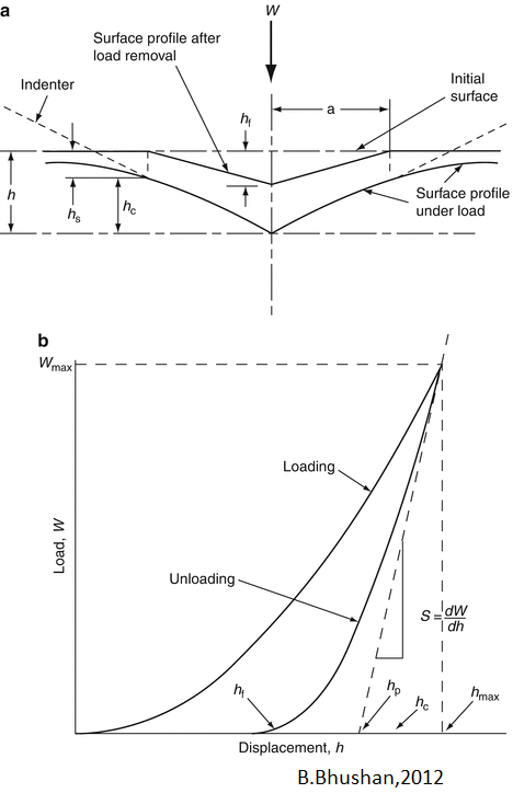
The coefficients for the polynomial fit is stored in a file. On the material to be tested, an indentation with a known force is made and the final depth is measured. This final depth is fitted into the stored polynomial fit to calculate an exact area for the indentation made in the test sample. This newly calculated area is then used to calculate the hardness and elastic modulus of test sample.
After performing the required calibrations, Ti-Au thin film samples were loaded onto the sample stage and the site required to perform the indentation test was selected using the optical microscope. A trapezoidal load function with each segment 10 seconds long was created to apply the maximum force of 5000μN, in a 4 by 4 grid pattern at 3 different locations. Hardness and elastic modulus were measured and averaged over the data points to achieve an overall hardness and elastic modulus value for the thin film sample.
Stay tuned with us to know more about the thin films deposited and the characterization results achieved….


Comments